Photo-led cap feeding, bowl feeding and cap presentation systems for UK capping lines01494 623015   sales@lancinguk.com
Automatic cap feeding systems

Automatic cap feeders for capping machinery.

Cap feeding systems specified around your closure, capper, target output and handover point — not just a generic feeder bowl.

Need the feeder to match your cap and capper?

Send cap samples, photos, target output and the downstream capping machine details. The quickest shortlist starts with real parts, not a generic speed figure.

Send cap details
Specification focus

Keep the capping machine supplied with correctly presented closures.

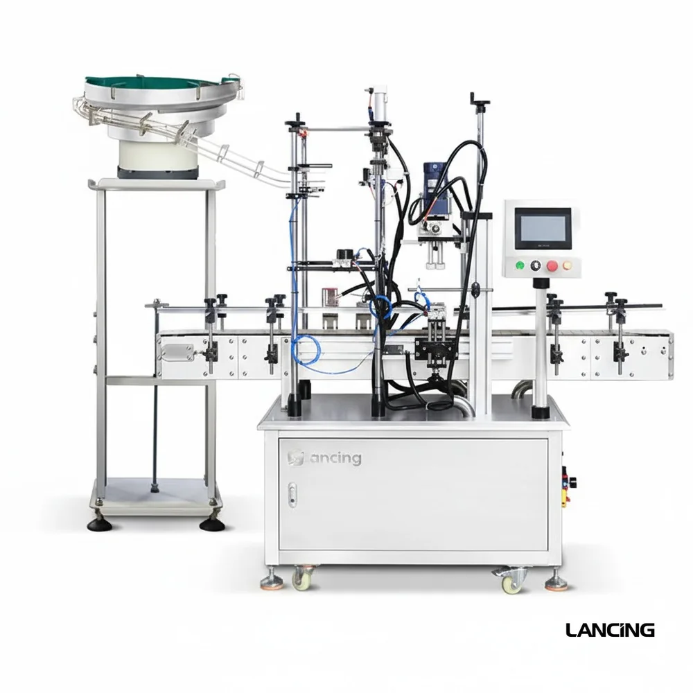
An automatic cap feeder removes the repeated manual task of placing each cap on the bottle or into the capper. The system normally combines bulk storage, controlled feeding, orientation and a final handover to the capping head.

The right route depends on the closure, not only the advertised line speed. A simple plastic screw cap may run through a hopper and elevator, while pumps, triggers and unusual closures often require custom tooling, extra control and careful bottle support.

Lancing can help compare bowl feeding, cap elevators, sorting tracks, chutes and sensors so the capper receives a consistent supply of usable caps.

Bulk cap storageHoppers and elevators reduce the frequency of operator loading and help keep the capper supplied.
Orientation before handoverTooling rejects or corrects wrong-way caps before they reach the chute or placement point.
Capper interfaceThe discharge point, height, controls and guarding are matched to the downstream machine.
Selection table

Information that changes the feeder design.

DetailWhy it mattersWhat to send
Closure geometryControls whether caps can be separated, sorted and held in a stable orientation.Photos, samples, diameter, height, skirt depth, material and any liner details.
Required presentationThe same cap may need different exit orientation depending on the capping head.Correct orientation, chute angle, pick point, capper type and discharge height.
Target outputThe feeder must exceed realistic production speed without flooding the track.Caps per minute, bottles per hour, planned shifts and expected efficiency.
Changeover rangeMultiple closures can require adjustable tooling or dedicated change parts.All cap sizes, SKU frequency and whether quick changeover is important.
Related systems

Move into the nearest feeder route.

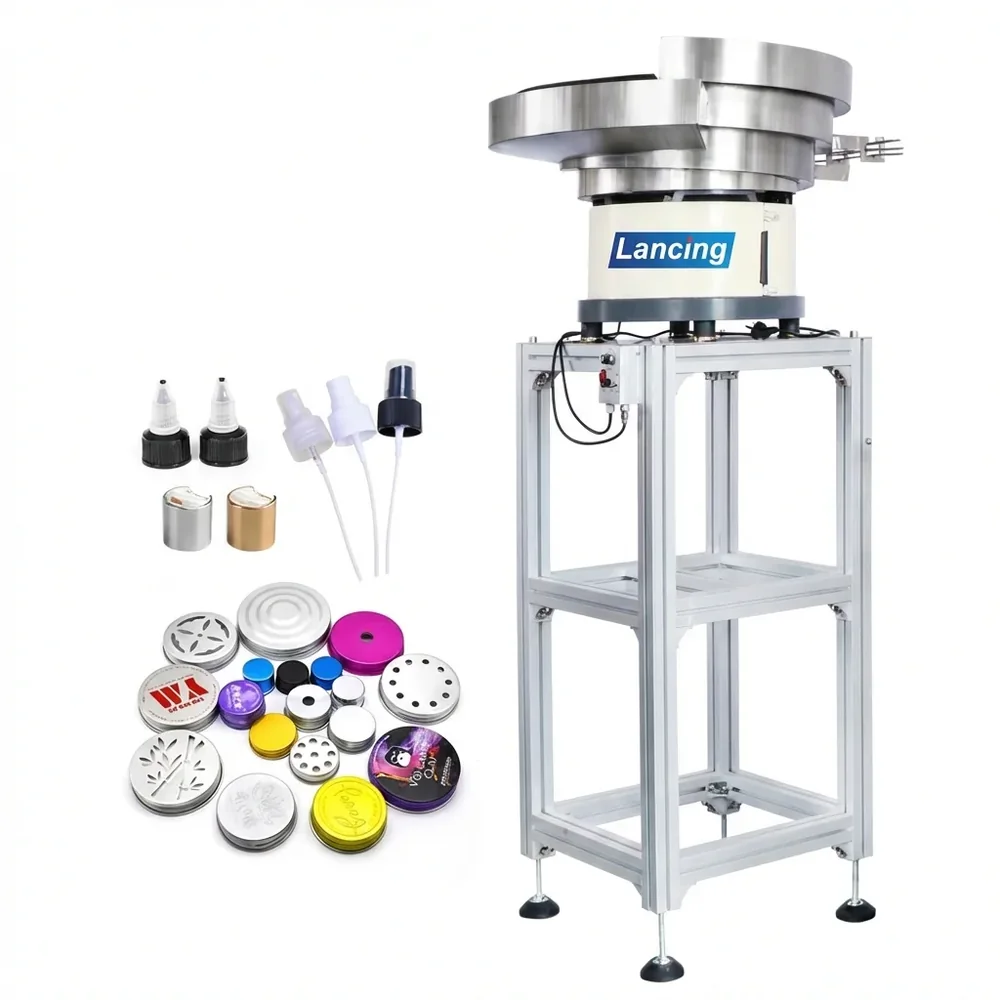
Cap feeder with closure samples
Cap feeders

Automatic cap feeders

Controlled cap supply for automatic and semi-automatic cappers.

Read more
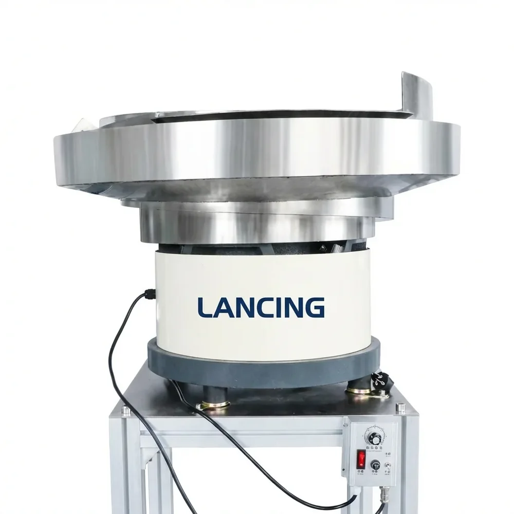
Vibratory bowl feeder close up
Bowl feeders

Vibratory bowl feeders

Bowl tooling and track design for sorting and orientation.

Read more
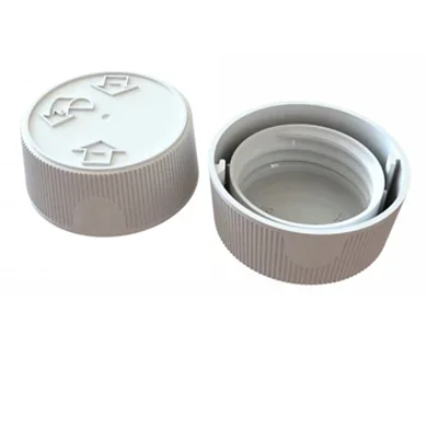
Plastic screw cap samples
Sorters

Cap sorters

Wrong-way rejection and closure presentation before capping.

Read more
Pump capping machine with bowl feeder
Special closures

Pump and trigger feeding

Feeding support for pumps, sprayers and difficult closures.

Read more
Connected Lancing routes

Built to sit beside the wider Lancing machinery network.

The site now links cap feeding intent to bowl feeder specification, capping machine selection and wider bottle-line planning.

Bowl feeding

Vibratory bowl feeder specification

Use the bowl feeder route when the cap or component needs sample-based tooling, orientation and a stable discharge point.

Visit bowlfeeders.co.uk
Capping

Capper selection and closure type

Use the capping machinery route when the project also needs screw, pump, trigger, ROPP, press-on or complete capping equipment.

Visit cappingmachinesuk.co.uk
Line planning

Filling, capping and labelling context

Use the Lancing UK route when the feeder is part of a wider packaging line, retrofit, installation or project-planning brief.

Visit lancinguk.online
FAQs

Questions about automatic cap feeders.

What is an automatic cap feeder?

An automatic cap feeder stores loose caps in bulk, sorts or orientates them, and delivers them to the capping machine through a chute, guide, pick point or placement route.

Which caps can be fed automatically?

Common applications include screw caps, flip-top caps, pumps, trigger sprayers, ROPP caps, crown caps and specialist closures, subject to sample assessment.

How fast can a cap feeder run?

Feed rate is application-specific. It depends on cap shape, orientation requirement, bowl or elevator design, chute length and the downstream capper speed.

Engineering selection detail

Automatic cap feeder selection should start with cap evidence, not a catalogue label.

The most useful cap feeder specification links closure behaviour, capper interface and production pattern. This section adds the compatibility and quotation checks normally needed before Lancing can recommend a route.

Closure shape

Geometry decides the feed route

Round screw caps, flip-tops, pumps, triggers and ROPP caps all present different risks around nesting, orientation, scuffing and discharge.

Compare closure feeders
Buffer control

Keep the capper supplied

The feeder should avoid starving the capper but also avoid flooding the chute or packing caps against the handover point.

Output-rate checks
Change parts

Plan format range early

Several caps may require adjustment, dedicated change parts or a separate feed path where size or orientation differences are too large.

Changeover guidance
Specification evidence

Information Lancing should check before final feeder selection.

These checks improve quotation quality without assuming unsupported speeds, capacities or format ranges.

CheckWhy it mattersUseful evidence to send
Cap dimensionsBasic dimensions influence bowl tooling, track width, chute design and changeover range.Diameter, height, skirt depth, thread detail, liner/tamper band and measured samples from each cap family.
Orientation featureA cap needs a usable feature for mechanical orientation or an alternative detection/reject method.Photos of top, underside and side profile, plus the required exit orientation into the capper.
Decorative surfacePrinted, metallic, soft-touch or gloss finishes may need gentler contact and scuffing checks.Finished production caps, not only plain development samples, when presentation quality matters.
Capper interfaceOutlet height, chute angle and cap control depend on the downstream capping machine.Capper model/photos, available space, guarding constraints and desired handover point.
Buyer questions

Practical questions before ordering a cap feeding system.

What makes an automatic cap feeder different from a bowl feeder?

A bowl feeder is one possible technology inside a cap feeding route. The complete automatic feeder may also include a hopper, elevator, chute, sensors, guards and controls.

What causes cap feeder unreliability?

Common causes include poor cap separation, wrong exit orientation, chute flooding, insufficient buffer, cap scuffing, sensor gaps or a handover point that does not suit the capper.

Can pumps and triggers be handled like screw caps?

Usually not. Pumps and triggers can have dip tubes, offset heads and tangling risk, so they need separate sample-led handling checks.

What should be confirmed before ordering?

Confirm cap samples, required orientation, bottle/cap combination, capper interface, target output, operator refill method and changeover range.

Can Lancing help with the capper as well?

Yes, where the feeder needs to be considered alongside automatic capping machinery and the wider packaging line.

Automatic feeder evidence

What changes an automatic cap feeder from a concept into a workable specification.

The safest automatic cap feeder route is based on the closure behaviour and the capping-machine handover. The same cap can need a different solution if the line uses a different capper, chute height, operator loading method or output target.

EvidenceDesign decision affectedRisk if missed
Production cap samplesBowl tooling, elevator route, track width, reject method and orientation check.Caps can nest, bridge, invert or scuff differently from sample photos.
Bottle and cap togetherCap placement method, chute exit, head clearance and bottle support.The feeder may deliver caps correctly but fail at the capper handover.
Refill and access preferenceHopper position, operator reach, low-level warning and guarding layout.The line may stop because caps cannot be replenished safely or quickly enough.
Changeover rangeAdjustable guides, change parts, dedicated bowl tooling or separate route.One quoted system may not practically cover the full closure set.
Operating checks

Throughput, buffer and jam recovery should be confirmed with the real cap.

A published speed without the closure, orientation and handover context is not enough. Lancing should be able to relate the feed route to the real capper demand and the operator plan.

Throughput

Match the capper demand

Target caps per minute, normal running speed and peak demand help decide whether the feeder should prioritise compactness, buffer or recovery margin.

Buffer

Avoid starvation and flooding

The chute and hopper should support the line without forcing too much cap pressure into the capper inlet or leaving the capper waiting for closures.

Recovery

Make stops obvious

Jam detection, cap-low alerts and accessible clearing points reduce the time lost when the cap supply is interrupted.

Is a higher feeder speed always better?

No. The feeder should comfortably support the capper without flooding the chute, damaging caps or making recovery harder for operators.

Should decorative caps be tested differently?

Yes. Gloss, printed, metallised or soft-touch closures should be checked for contact marks and scuffing risk on the proposed route.

Can an automatic cap feeder be added later?

Often it can, but the capper must have space, a suitable handover point and a practical control interface for the feeder.

Selection framework

Choose the cap feeder as a chain of functions.

Bulk storage, singulation, orientation, buffer, chute control and final presentation can be supplied by one machine or several connected modules. Define each function before comparing equipment.

FunctionQuestion to answerEvidence
Store and meterHow will operators load caps and how much short-term buffer is needed?Shift pattern, refill access, cap supply container and acceptable intervention.
Separate and orientateWhich cap feature can create the required exit orientation?Production samples, drawings, liner/tamper detail and required leading face.
Reject and recoverWhat happens to wrong-way, doubled, damaged or foreign parts?Quality limits, recirculation decision, reject destination and fault logic.
Accumulate and deliverHow will the cap remain controlled between feeder and capper?Chute route, discharge height, cap-in-chute sensing and capper demand.
Stop and restartHow should the system respond to low caps, blockage or downstream stop?Control narrative, shared signals, operator actions and safe recovery method.
Project risk

Resolve the difficult cap and interface questions before fabrication.

Samples

Use production variation

Include caps from normal supply, not only ideal samples. Liners, tamper bands, decoration and mould variation can change feed behaviour.

Layout

Fix the handover first

Discharge height, chute angle, capper position, guard opening and operator access should be agreed before the stand and hopper are fixed.

Acceptance

Test more than steady flow

Plan low-cap, stop, restart, reject, jam and changeover scenarios so recovery is part of the accepted result.

Automatic feeding questions

Questions about the boundary of an automatic cap feeding system.

The term “cap feeder” can cover different amounts of equipment. These answers help define the supply, orientation, transfer and placement boundary before quotation.

Does an automatic cap feeder place the cap or only present it?

An automatic cap feeder may only sort and deliver caps to a chute or pick point, or it may form part of a wider system that also releases or places each closure. The project boundary must state where the feeder ends and where the capping machine, escapement or placement mechanism takes control.

Defining that boundary prevents gaps around cap release, bottle timing, missed-cap detection and responsibility for the final handover. The same cap can need a different outlet when used with a spindle capper, chuck capper, indexed head or rotary machine.

Compare cap handover methods

What makes cap feeding reliable over a full production run?

Reliable cap feeding depends on more than a steady stream during a short demonstration. The system must separate variable production caps, reject unsuitable orientations, maintain a controlled buffer, follow capper demand and restart after normal stops without flooding the track or damaging queued closures.

A useful trial includes replenishment, low-cap conditions, planned stops, recovery, wrong-way rejection, representative cap variation and inspection for marks or damaged features. Sustainable operation should be agreed against the actual line behaviour rather than a feeder running in isolation.

Plan practical acceptance checks

How should future cap formats be included in the first specification?

List every known current and planned cap family before tooling is fixed. Compare diameter, height, skirt depth, orientation features, centre of gravity, finish, liner, tamper band and required outlet condition, then decide which settings can be shared and which formats need dedicated change parts.

A future format should not be accepted only because its nominal diameter is similar. Each agreed format needs its own sample evidence, settings or tooling definition and first-off checks so flexibility is designed rather than assumed.

Plan multi-format changeover

What should the feeder do when the capper cannot accept another cap?

The feeder should respond to an agreed demand or full-queue condition before caps are forced into the chute or recirculated unnecessarily. Depending on the system, this may stop or modulate the hopper, elevator, bowl or sorter while preserving a usable queue for restart.

The control sequence should define sensor position, permitted accumulation, fault handling and restart order. It should also distinguish a normal capper stop from a genuine jam so operators are not asked to clear a healthy buffer.

See line-stop and restart control
Project brief

Define the complete automatic cap feeding boundary.

A complete cap feeder scope can include bulk storage, metering, orientation, queue control, capper handover, sensors, guarding, changeover and operator recovery.

BoundaryWhat to confirmBest supporting guide
RequirementCap type, bottle and cap combination, required outlet condition and future formats.Cap feeder URS checklist
EvidenceProduction samples, photos, drawings, orientation needs and known difficult caps.Cap feeder trial plan
ControlsCap demand, cap-in-chute, line stop, fault recovery and operator messages.Controls and I/O guide
HandoverChute route, outlet height, cap queue, cap release and capper interface.Feeder-to-capper handover
Specification depth

Checks that move a cap feeder from concept to reliable production.

A cap feeder quote is strongest when it describes the difficult behaviours as well as the cap size. The following points help Lancing understand whether the line needs a straightforward feed route or additional control.

Risk areaWhat to checkUseful route
Static and clingWhether lightweight caps bridge, attract dust or cling to guides during dry running.Anti-static cap feeding
Nested or doubled capsWhether caps arrive one at a time or overlap before the sorter can reject them.Nesting and shingling checks
Cap verificationWhether the line needs cap presence, orientation, colour or correct-cap confirmation before handover.Verification and inspection
Layout and accessWhether the hopper, bowl, chute, guard opening and loading point fit the real line.Layout and footprint planning
Evidence for acceptanceWhat photos, videos, sample records and recovery notes should support the quotation.Test evidence pack
CallQuote