Photo-led cap feeding, bowl feeding and cap presentation systems for UK capping lines01494 623015   sales@lancinguk.com
Vibratory bowl feeding

Vibratory bowl feeders for caps and closures.

Custom bowl feeder systems that sort, orient and feed caps, closures and components into capping machines or automated pick points.

Need the feeder to match your cap and capper?

Send cap samples, photos, target output and the downstream capping machine details. The quickest shortlist starts with real parts, not a generic speed figure.

Send cap details
Specification focus

Use bowl feeding when orientation needs controlled tooling.

A vibratory bowl feeder is useful when caps or closure components must be presented in a repeatable orientation before the next automatic operation. The bowl, track, tooling gates and discharge chute are configured around the real part.

For cap feeding, the bowl has to do more than move parts. It must separate loose caps, reject inverted or wrongly presented closures and maintain enough flow to keep the capper supplied without filling the track too aggressively.

Bowl feeder design is sample-led. The most useful enquiry includes physical caps, photos, dimensions, material, target rate and the required exit orientation.

Custom track geometryTrack and tooling are shaped around the cap, closure or production part.
Orientation and rejectionWrong-way caps can be rejected or corrected before the outlet.
Line-ready dischargeChutes, stands and controls are matched to the capper or pick point.
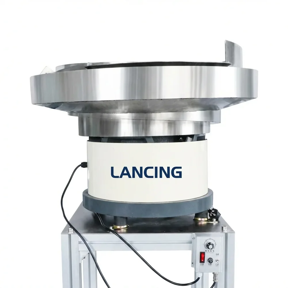
Close up of a Lancing vibratory bowl feeder
Close-up

Bowl and drive unit

A closer view of the bowl and drive unit used for controlled part movement.

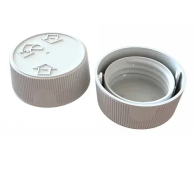
Plastic screw cap samples
Samples

Cap samples

Sample caps help confirm whether the bowl route and tooling are practical.

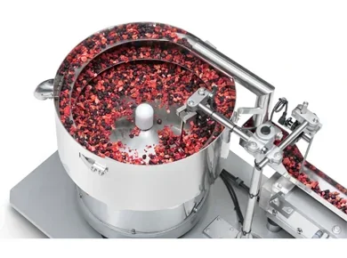
Bowl feeder handling small red components
Components

Component feeding

The same sample-led logic applies to small parts and components as well as caps.

Selection table

Information that changes the feeder design.

DetailWhy it mattersWhat to send
Closure geometryControls whether caps can be separated, sorted and held in a stable orientation.Photos, samples, diameter, height, skirt depth, material and any liner details.
Required presentationThe same cap may need different exit orientation depending on the capping head.Correct orientation, chute angle, pick point, capper type and discharge height.
Target outputThe feeder must exceed realistic production speed without flooding the track.Caps per minute, bottles per hour, planned shifts and expected efficiency.
Changeover rangeMultiple closures can require adjustable tooling or dedicated change parts.All cap sizes, SKU frequency and whether quick changeover is important.
Connected Lancing routes

Built to sit beside the wider Lancing machinery network.

The site now links cap feeding intent to bowl feeder specification, capping machine selection and wider bottle-line planning.

Bowl feeding

Vibratory bowl feeder specification

Use the bowl feeder route when the cap or component needs sample-based tooling, orientation and a stable discharge point.

Visit bowlfeeders.co.uk
Capping

Capper selection and closure type

Use the capping machinery route when the project also needs screw, pump, trigger, ROPP, press-on or complete capping equipment.

Visit cappingmachinesuk.co.uk
Line planning

Filling, capping and labelling context

Use the Lancing UK route when the feeder is part of a wider packaging line, retrofit, installation or project-planning brief.

Visit lancinguk.online
FAQs

Questions about vibratory bowl feeders.

What does a vibratory bowl feeder do?

A vibratory bowl feeder uses vibration, track geometry and tooling to move loose parts into a consistent orientation before discharge.

Can bowl feeders handle pumps and triggers?

Sometimes, but pumps and triggers need sample assessment because tubes, nozzles and offset shapes can tangle or destabilise.

Can the bowl be adjusted for several caps?

Some ranges can be adjustable, but multiple cap shapes may need dedicated tooling or change parts.

Engineering selection detail

Vibratory cap bowl feeder design depends on the track, reject logic and handover.

A bowl feeder can be the right cap feeding route when the cap has enough geometry for reliable orientation and the downstream capper can accept a controlled discharge. The checks below keep the decision focused on cap and closure behaviour while retaining the capper interface as part of the specification.

Track tooling

Tooling is part-specific

The track, gates and rejects are shaped around the cap, so small differences in skirt, ribs or liner can change the design.

Cap feed bowl route
Cap quality

Avoid avoidable scuffing

Decorative caps and visible closures should be checked for contact marks, track pressure and repeated recirculation.

Gentle handling checks
Discharge

Match the capper chute

A stable bowl exit still needs a compatible chute, height, angle and cap-in-chute control before the capping head.

Chute checks
Specification evidence

Information Lancing should check before final feeder selection.

These checks improve quotation quality without assuming unsupported speeds, capacities or format ranges.

CheckWhy it mattersUseful evidence to send
Cap orientationThe bowl needs a repeatable way to reject or correct wrong-way caps.Required orientation, top/underside photos and samples showing the usable orientation feature.
Sample variationProduction variation can affect track performance more than one perfect sample.Samples from normal production batches, including any colour, finish or supplier variation.
Noise and accessBowl size, speed and guards influence operator access, cleaning and maintenance.Installation space, operator side, access limits and cleaning expectations.
Outlet controlThe downstream chute must not overload or starve the capper.Capper photos, chute route, handover height and preferred sensor/control arrangement.
Buyer questions

Practical questions before ordering a cap feeding system.

When is a vibratory bowl feeder suitable for caps?

It is suitable when the cap can be separated, oriented and discharged reliably using tooling around the physical part.

What can make a bowl feeder unsuitable?

Very awkward closure geometry, high scuffing sensitivity, excessive tangling, poor orientation features or limited space can point to another feeding route.

Do bowl feeders need real samples?

Yes. Samples are important because the bowl track and reject features are designed around how the cap behaves in motion.

Can one bowl run different cap sizes?

Sometimes, but the format range must be checked carefully and may require adjustment points or dedicated change parts.

When should this cap-feeding guide be used instead of a general bowl-feeder guide?

Use this guide when the part is a cap or closure feeding into a capping line. Use the wider bowl-feeder route when the application concerns general industrial components rather than closure presentation.

Bowl feeder selection

When a vibratory bowl is the right cap feeding method.

A vibratory bowl is useful when the cap has a feature that can be used to sort, reject or present it reliably. It is not automatically the best route for every closure, especially where pumps, triggers, tubes or delicate decorative finishes create handling risks.

Cap featureWhat the bowl can useWhat Lancing should check
Thread, skirt or rib detailTooling can help reject wrong orientation or stabilise travel.Whether the feature is consistent enough across production caps.
Open and closed facesThe bowl can use weight, centre of gravity or face shape for orientation.Whether caps flip, bounce or re-orientate in the discharge chute.
Decorative or polished surfaceContact route can be controlled where practical.Whether the finish tolerates vibration, tracks and accumulation.
Wide format rangeAdjustment or change parts may be possible for some families.Whether each cap needs a different bowl, rail or reject feature.
Discharge and operation

The bowl is only one part of the cap feeding route.

For capping lines, the discharge chute, buffer, low-level signals and capper interface are just as important as the bowl tooling. A cap that leaves the bowl correctly still needs to arrive at the capper in the right orientation and at the right time.

Chute

Protect the handover

Chute width, angle, rail profile and back pressure should be matched to the cap and capper inlet, especially where caps can shingle or turn sideways.

Chute guidance
Sensors

Control the buffer

Cap-in-chute and low-level checks help the bowl pause, restart or alert the operator before the downstream capper is starved.

Sensor checks
Recovery

Design for clearing

Access to likely bridging or jam points should be considered before the line is installed, not after the first production stoppage.

Jam recovery
Does every cap bowl need dedicated tooling?

Many cap bowls are sample-led and may need dedicated or adjustable tooling. The answer depends on the cap family and changeover expectations.

Can a bowl feeder handle caps with liners?

It may be possible, but the liner can affect weight, centre of gravity and friction, so the production cap should be assessed rather than assuming from the shell shape.

When should another technology be considered?

Consider an elevator, sorter, presenter or custom route when the bowl would create excessive noise, scuffing, tangling, changeover complexity or footprint.

Technology boundary

A vibratory bowl is one cap-sorting method, not the default answer for every closure.

The bowl route is strongest when part-specific tooling can use reliable cap features to reject wrong orientations and create a stable discharge. Other caps may suit an elevator/orientator, rotary sorter or special presenter better.

Good evidence

Repeatable geometry

Ribs, skirt, thread, hinge, liner or centre of gravity may provide features for tooling, but they must be checked on real production caps.

Watch point

Visible surface contact

Decorated and easily marked caps need trials through the full bowl, reject and chute route, not only a visual check at the outlet.

Alternative

Bulk lift plus another sorter

An elevator can improve loading and buffer while a separate orientator performs the precision sorting task.

Bowl orientation questions

Questions about how a vibratory bowl orientates real closures.

Bowl movement is only one part of the result. The usable orientation comes from the relationship between the cap, track, tooling, reject route and outlet.

How does bowl tooling create the correct cap orientation?

Bowl tooling uses the cap’s geometry, balance and behaviour on the track to allow acceptable orientations to continue and return unsuitable ones for another pass. Gates, rails, cut-outs and track transitions are developed around the real closure and the exact attitude required at the outlet.

The aim is not simply to make caps move faster. Tooling should separate overlaps, control recirculation and preserve the chosen orientation through the discharge. Production samples are needed because mould variation, liners, decoration and tamper features can change how a cap reacts.

Compare cap sorting methods

What cap features can a vibratory bowl use for orientation?

A vibratory bowl may use differences in top and open-face profile, skirt depth, rim shape, hinge position, nozzle form, ribs, weight distribution or another repeatable asymmetry. The useful feature must remain consistent across normal production and must not require contact that damages a functional or visible surface.

Symmetrical or very shallow caps can offer fewer reliable mechanical cues, while pumps and triggers introduce offset heads and dip tubes. The feasible route should therefore be established by sample behaviour rather than by assigning every cap to a generic bowl category.

Review closure orientation factors

When can vibration damage or mark a closure?

Marking risk increases when visible surfaces repeatedly contact the bowl, track, other caps or reject tooling, particularly with decorated, metallised, gloss or soft-touch finishes. Thin tamper features, loose liners and delicate dispensing parts can also be affected by uncontrolled circulation or unsuitable contact points.

The trial should define what appearance and functional condition is acceptable, inspect caps after realistic circulation and check the effect of bowl loading and recirculation. Gentle-handling measures depend on the closure and cannot be confirmed from finish descriptions alone.

Assess sensitive cap features

What should be observed during a bowl-feeder trial?

Observe separation in bulk, the proportion and route of rejected orientations, recirculation behaviour, stable outlet presentation, cap condition and the response to starts, stops and replenishment. The trial should include ordinary production variation rather than only selected ideal samples.

Also check whether caps remain correctly oriented after leaving the bowl, because a successful bowl outlet can still be undermined by an unstable chute or handover. Record the tested settings and the evidence needed to repeat the result after changeover.

Prepare representative trial samples
Bowl feeder evidence

Prove the tooling route before treating a bowl as the answer.

A vibratory bowl can be the right route for many caps, but the sample, orientation target, noise limit, scuffing tolerance and discharge point should be checked before the layout is fixed.

What should a bowl trial show?

The trial should show whether the closure can separate from bulk, climb or progress consistently, reject wrong-way positions and reach the outlet without unacceptable scuffing or instability.

Plan a cap feeder trial

What should be reviewed before build?

Check bowl diameter, tooling boundary, discharge height, chute route, operator access, control signals and change parts against the real capping line.

Use the design review guide
Bowl tooling detail

Extra bowl-feeder variables for caps and closures.

A vibratory bowl feeder has to work with cap surface condition, mass distribution and production variation. Small differences in cap finish or storage can change how the closure climbs, separates and exits the track.

When should static be considered in a vibratory cap bowl?

Static should be considered when caps are lightweight, plastic, broad-faced, dry-stored or already known to cling in handling. The feeder route may need changes to surface contact, track material, control settings or operating conditions.

Read anti-static guidance

Why do some caps shingle in a bowl track?

Shingling can happen when caps overlap or ride partly on each other instead of separating into a single file. The risk depends on skirt depth, sidewall profile, lid shape, friction and track transitions.

Check shingling risks

How does bowl position affect the capper handover?

Outlet height, chute fall, queue length, stand position and guard access can decide whether the bowl works comfortably with the capping machine. The physical layout should be agreed before the bowl stand is fixed.

Plan the feeder layout

What should be recorded during a bowl-feeding trial?

Record the cap sample, the correct outlet orientation, wrong-way rejection, any visible marks, nested-cap behaviour, stop/restart performance and the condition of caps after recirculation.

Prepare test evidence
CallQuote