Photo-led cap feeding, bowl feeding and cap presentation systems for UK capping lines01494 623015   sales@lancinguk.com
Pump and trigger feeding

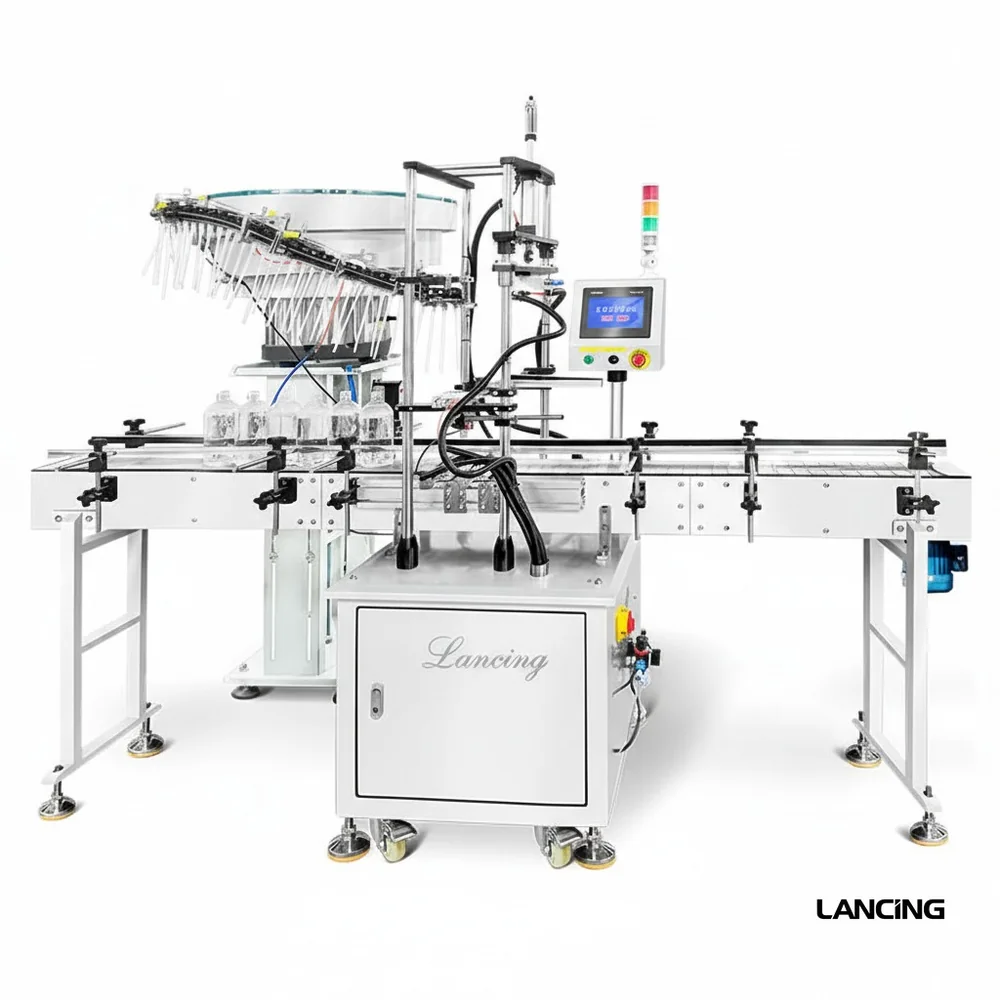
Pump, trigger and sprayer feeding systems.

Feeding systems for difficult closure shapes used on cosmetics, personal care, household cleaning, chemical and contract packing lines.

Need the feeder to match your cap and capper?

Send cap samples, photos, target output and the downstream capping machine details. The quickest shortlist starts with real parts, not a generic speed figure.

Send cap details
Specification focus

Control awkward closures before they reach the bottle.

Pumps, triggers and sprayers can be some of the most difficult closures to automate because they are tall, directional and prone to tangling. A feeder that works for a round plastic cap may not work for a pump with a long tube.

The feeding route may need controlled lanes, bowl tooling, guides, placement support and extra attention to bottle stability. The capper also has to tighten or press the closure without pulling the bottle out of position.

For a practical shortlist, send the complete closure with tube, sample bottles, photos of the existing capper if retrofitting and the realistic target output.

Tube and head controlDip tubes, nozzles and handles must not tangle before handover.
Directional presentationThe closure may need to point a specific way before placement or tightening.
Line integrationSensors and guides help the feeder and capper run as one system.
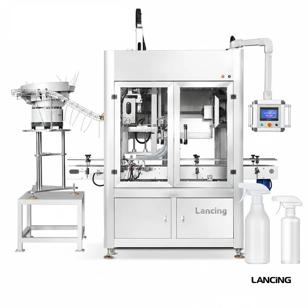
Trigger sprayer capping machine with feeder
Triggers

Trigger sprayer capping

Feeding and capping route for household and care bottles.

Read more
Pump cap feeding line with conveyor
Pumps

Pump cap feeding

Specialist feeder route for dispenser and pump closures.

Read more
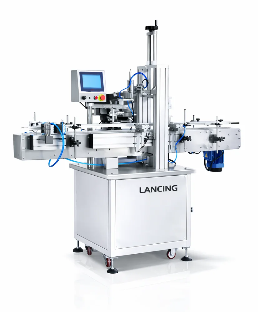
Cap pressing machine with feeder
Press-on

Press cap feeding

Press-on and lid-style closures need repeatable presentation before seating.

Read more
Selection table

Information that changes the feeder design.

DetailWhy it mattersWhat to send
Closure geometryControls whether caps can be separated, sorted and held in a stable orientation.Photos, samples, diameter, height, skirt depth, material and any liner details.
Required presentationThe same cap may need different exit orientation depending on the capping head.Correct orientation, chute angle, pick point, capper type and discharge height.
Target outputThe feeder must exceed realistic production speed without flooding the track.Caps per minute, bottles per hour, planned shifts and expected efficiency.
Changeover rangeMultiple closures can require adjustable tooling or dedicated change parts.All cap sizes, SKU frequency and whether quick changeover is important.
Connected Lancing routes

Built to sit beside the wider Lancing machinery network.

The site now links cap feeding intent to bowl feeder specification, capping machine selection and wider bottle-line planning.

Bowl feeding

Vibratory bowl feeder specification

Use the bowl feeder route when the cap or component needs sample-based tooling, orientation and a stable discharge point.

Visit bowlfeeders.co.uk
Capping

Capper selection and closure type

Use the capping machinery route when the project also needs screw, pump, trigger, ROPP, press-on or complete capping equipment.

Visit cappingmachinesuk.co.uk
Line planning

Filling, capping and labelling context

Use the Lancing UK route when the feeder is part of a wider packaging line, retrofit, installation or project-planning brief.

Visit lancinguk.online
FAQs

Questions about pump and trigger feeders.

Can automatic feeders handle trigger sprayers?

Yes in many cases, but trigger sprayers need sample-based assessment because head shape and tube length affect orientation.

What details matter for pump feeders?

Tube length, pump head direction, cap diameter, bottle stability, target speed and how the capper grips the closure.

Are these systems only for cosmetics?

No. They are also common in household cleaning, chemical, personal care and contract packing lines.

Engineering selection detail

Pump and trigger feeders need tube control, head orientation and careful handover.

Pumps and triggers usually have more failure modes than round caps. Dip tubes, trigger handles, nozzles and decorative heads must be assessed together with the bottle and capping machine.

Tube control

Dip tubes change the handling route

Tube length, stiffness and curl can decide whether a closure can be fed automatically or needs a different presentation method.

Closure feeders
Head direction

Orientation matters before placement

Trigger handles and pump nozzles may need to face a particular way for the capper or finished pack.

Orientation systems
Bottle support

Placement depends on bottle stability

Tall or lightweight bottles can move during pump placement, so conveyor support and guides are part of the feeder conversation.

Integration checks
Specification evidence

Information Lancing should check before final feeder selection.

These checks improve quotation quality without assuming unsupported speeds, capacities or format ranges.

CheckWhy it mattersUseful evidence to send
Tube length and flexibilityLong or flexible tubes can tangle and change the feed route.Pump/trigger samples with production dip tubes, not tube-free samples.
Head geometryOffset heads affect orientation and guide design.Side, top and underside photos plus the required head/nozzle direction.
Bottle detailsThe bottle decides placement stability and clearance.Bottle samples, neck finish, height, diameter and whether bottles are filled at capping.
ChangeoverSmall differences between pump families may require different guides.All pump and trigger variants intended for the same machine.
Buyer questions

Practical questions before ordering a cap feeding system.

Can pump caps be fed automatically?

Often yes, but tube length, head shape and required orientation must be assessed with real samples.

Can triggers be fed in the same bowl as screw caps?

Usually this needs separate assessment because triggers behave differently from round screw caps in bulk and on a track.

What should I send for a pump feeder quote?

Send pump samples with tubes fitted, matching bottles, required head orientation, capper details and output target.

What causes pump feeder jams?

Common causes include tube tangling, head misorientation, chute pinch points, overfilling and unstable bottle presentation.

Should output be confirmed by a trial?

Yes where output is important, because tube and head behaviour can make theoretical rates unreliable.

Dip tube evidence

Pumps and triggers should be treated as assemblies, not simple caps.

Pump and trigger feeders need more evidence because the head, stem, dip tube, nozzle and tube memory can all affect feeding. A route that works for a screw cap may not control a long or curled tube reliably.

FeatureFeeding issueEvidence to send
Dip tube length and curlTubes can tangle, hook into other closures or drag on the chute.Production pumps/triggers with tubes fitted, not just heads.
Head orientationThe outlet, trigger lever or pump head may need to face a particular direction.Required orientation at bottle entry and photos of the capper placement route.
Bottle stabilityInsertion forces and tube behaviour can move light or narrow bottles.Bottle samples, fill condition for testing and conveyor support details.
Decorative finishSprayers and pumps may show scuffs on collars, heads or shrouds.Production-finish samples and marking tolerance.
Handover checks

The feeder, bottle handling and capping head must be considered together.

For pumps and triggers, the handover is often the real engineering problem. The system may need tube control, bottle support and a consistent presentation point before the capper can tighten or press the closure.

Tube control

Avoid dragging and snagging

Tube path, insertion angle and guide surfaces should be assessed with real tubes because packaging-room handling can change tube memory.

Spray pump route
Bottle support

Hold the container steady

Tall or light bottles may need guide rails, timing screws, starwheels or additional support while the tube and closure are presented.

Line integration
Capper route

Use the specialist capper site when needed

Where the project includes tightening method, torque, head design or pump/trigger capper selection, the capper-specific Lancing route should be used as well.

Capping machinery route
Why are pump and trigger feeders harder than screw cap feeders?

They often have offset heads, levers, nozzles and dip tubes that can tangle or require a controlled insertion path.

Should samples include the dip tube?

Yes. The tube length, curve and stiffness are central to the feeding and handover check.

Can one route handle both pumps and triggers?

Sometimes, but it depends on head geometry, tube behaviour, orientation requirement and acceptable changeover method.

Dip-tube trial

Test the complete pump or trigger assembly, not only the head.

Tube length, stiffness, curl, cut end, lock position and head offset can change how assemblies tangle, separate and arrive at the bottle.

Trial variableWhy it mattersWhat to provide
Dip tubeLong or curved tubes can hook, cross and resist separation.Production tube length, material, cut end and any length tolerance.
Head orientationTriggers and pump spouts may need a controlled direction before placement or final tightening.Required direction at pick-up, placement and completed bottle.
Actuator conditionLocked, unlocked or capped actuators can behave differently in bulk.The exact condition supplied to production and any protective overcap.
Bottle supportThe closure may need to be guided while the tube enters the neck and the head is placed.Representative bottle, fill condition, neck details and conveyor handling.
Finish and damageVisible heads and nozzles may scuff or deform during repeated recirculation.Appearance limits and samples with production decoration.
Pump and trigger questions

Questions about dip tubes, head direction and automatic placement.

Pumps and triggers must be assessed as complete assemblies because the tube, head and bottle interface can all change the feeding route.

Why must the dip tube be included in a pump or trigger trial?

The dip tube changes the assembly’s length, balance, tangling behaviour and clearance through every guide and transfer point. Testing only the pump or trigger head can hide tube snagging, dragging, crossing, kinking or interference that appears when complete production closures are handled in bulk.

Use the intended tube material and length range, including normal variation, and inspect the tube after circulation and placement. The feeder route should protect the complete assembly while maintaining the head orientation required by the capping process.

Prepare complete closure samples

How is trigger-head orientation defined for the capping machine?

Trigger-head orientation should be described relative to the bottle, conveyor direction and placement mechanism, for example the nozzle direction required when the trigger reaches the bottle neck. A clear drawing or marked sample is safer than terms such as “forward” without a line reference.

The feeder must preserve that orientation through the outlet and the capper must control the bottle while the assembly is placed. If the final direction is created after placement, that responsibility and motion should be separated from the feeder specification.

Define the final presentation point

What bottle-handling information affects automatic pump placement?

Automatic pump placement depends on the bottle neck, container shape, stability, filled condition, conveyor guides, spacing method and the way the bottle is held at the application point. A tall or flexible bottle may need different support from a short rigid container even when the pump is unchanged.

Send the real bottle and pump combination, line direction, capper or placement-head details and photos of the bottle-control area. The feeder cannot be confirmed independently from the position and stability of the container receiving the dip tube and closure.

Plan bottle, feeder and capper integration

When might assisted placement be safer than full automatic feeding?

Assisted placement may be the better route for low-volume production, frequent pump changes, fragile or highly variable dip tubes, or an assembly that has not shown repeatable automatic separation and presentation. It can remove the most difficult manual motion without adding a complex bulk-feeding stage.

The choice should be based on production pattern, operator task, bottle stability and trial evidence. Space and interfaces can still be planned so a later automatic feeder can be added if demand and closure consistency justify it.

Compare automation levels
Pump and trigger evidence

Treat dip tubes and offset heads as the main handling risk.

Pump and trigger closures need more than cap diameter checks because tube length, tube stiffness, head balance and decoration can change how the closure separates and presents.

Trial the actual tube

Use production closures with the real dip tube fitted. Tubes can tangle, trail, catch or alter centre of gravity in ways that are not visible from a cap drawing alone.

Plan a sample trial

Define operator recovery

Operators should know whether to clear a tube fault at the hopper, bowl, chute, reject point or capper handover, and when to stop calling it a feeder fault.

Training checklist

Control the handover

Tube orientation and queue control should be discussed with the capper interface so the placement route does not create twist, drag or unstable bottles.

Controls and I/O
Dip-tube handling

Additional checks for pumps, triggers and sprayers.

Pump and trigger closures combine head orientation with a tube or actuator that can tangle, spring back or catch. That makes evidence and line layout more important than a simple cap-size comparison.

Should tube direction or cap type be verified before handover?

Verification may be useful where a tube direction, trigger head, colour variant or closure family must be confirmed before the bottle reaches the capping head.

Plan verification

Why does feeder layout matter for trigger sprayers?

The chute path, bottle position and handover point must avoid bending, trapping or forcing the tube. Space around the capper should be reviewed with real bottle and trigger samples.

Review layout requirements

What evidence helps prove pump or trigger feeding?

Photos or video should record tube handling, head orientation, capper pickup, missed presentations, scuffing, recirculation and restart behaviour.

Prepare evidence

Can pumps and triggers be affected by static or surface finish?

Plastic trigger bodies and broad surfaces can be affected by friction and static, especially where tubes or actuators touch each other in bulk. Sample testing should include normal packaging and storage conditions.

Anti-static checks
CallQuote