Photo-led cap feeding, bowl feeding and cap presentation systems for UK capping lines01494 623015   sales@lancinguk.com
Line integration

Cap feeder integration for reliable capping lines.

Connect the feeder, sorter, chute, capper and conveyor so the capping stage runs as one controlled system.

Need the feeder to match your cap and capper?

Send cap samples, photos, target output and the downstream capping machine details. The quickest shortlist starts with real parts, not a generic speed figure.

Send cap details
Specification focus

A feeder only works properly when the interface is right.

Cap feeder integration is where many line reliability problems are solved. The bowl or elevator can be correctly selected, but the line will still stop if caps arrive at the wrong height, the chute overfills or the capper starts without a stable cap supply.

Integration checks include mechanical handover, electrical controls, sensor positions, guarding, operator access, cleaning access and whether the feeder should run continuously or follow the capper demand.

For retrofits, photos and measurements of the existing capper are essential. For new lines, the feeder should be planned alongside the filling, capping, labelling and conveying route.

Mechanical interfaceOutlet height, chute path, guide widths, guarding and maintenance access.
Controls interfaceStart-stop signals, level sensors, cap-in-chute detection and fault handling.
Line flowConveyor speed, bottle spacing, accumulation and operator access around the capping area.
CommissioningRun trials with real caps and bottles before final settings are accepted.
Selection table

Information that changes the feeder design.

DetailWhy it mattersWhat to send
Closure geometryControls whether caps can be separated, sorted and held in a stable orientation.Photos, samples, diameter, height, skirt depth, material and any liner details.
Required presentationThe same cap may need different exit orientation depending on the capping head.Correct orientation, chute angle, pick point, capper type and discharge height.
Target outputThe feeder must exceed realistic production speed without flooding the track.Caps per minute, bottles per hour, planned shifts and expected efficiency.
Changeover rangeMultiple closures can require adjustable tooling or dedicated change parts.All cap sizes, SKU frequency and whether quick changeover is important.
Related systems

Move into the nearest feeder route.

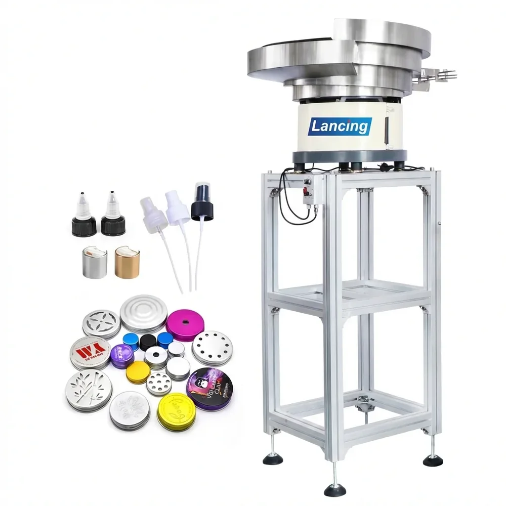
Cap feeder with closure samples
Cap feeders

Automatic cap feeders

Controlled cap supply for automatic and semi-automatic cappers.

Read more
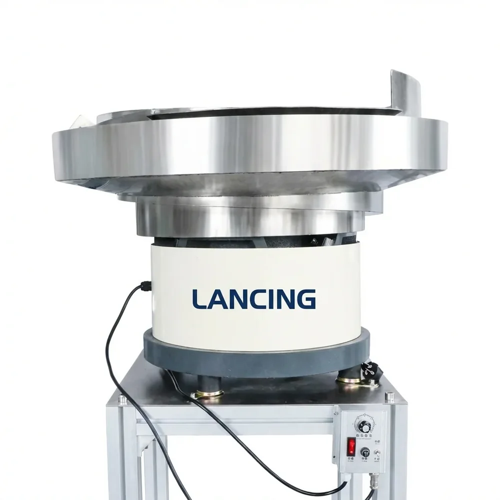
Vibratory bowl feeder close up
Bowl feeders

Vibratory bowl feeders

Bowl tooling and track design for sorting and orientation.

Read more
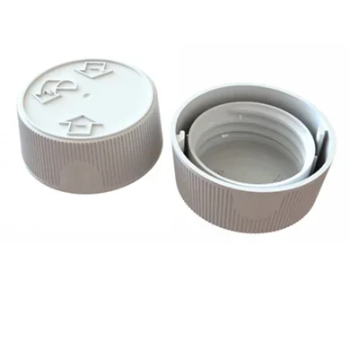
Plastic screw cap samples
Sorters

Cap sorters

Wrong-way rejection and closure presentation before capping.

Read more
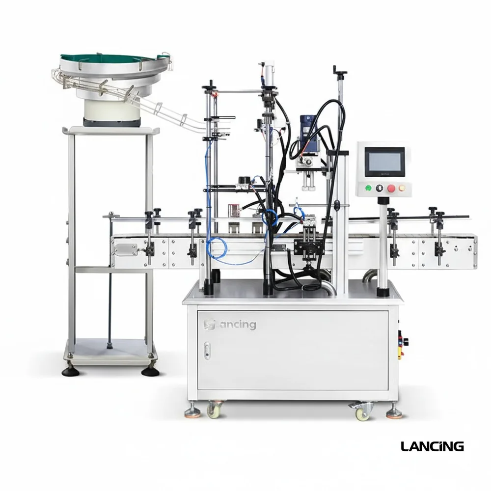
Pump capping machine with bowl feeder
Special closures

Pump and trigger feeding

Feeding support for pumps, sprayers and difficult closures.

Read more
Connected Lancing routes

Built to sit beside the wider Lancing machinery network.

The site now links cap feeding intent to bowl feeder specification, capping machine selection and wider bottle-line planning.

Bowl feeding

Vibratory bowl feeder specification

Use the bowl feeder route when the cap or component needs sample-based tooling, orientation and a stable discharge point.

Visit bowlfeeders.co.uk
Capping

Capper selection and closure type

Use the capping machinery route when the project also needs screw, pump, trigger, ROPP, press-on or complete capping equipment.

Visit cappingmachinesuk.co.uk
Line planning

Filling, capping and labelling context

Use the Lancing UK route when the feeder is part of a wider packaging line, retrofit, installation or project-planning brief.

Visit lancinguk.online
FAQs

Questions about integration.

What signals are useful between feeder and capper?

Level control, cap-in-chute, run permissive, fault and emergency stop integration are common interfaces.

Can Lancing integrate a feeder with an existing machine?

Often yes. The current capper layout, space, controls and handover method must be checked first.

What causes integration problems?

Common issues include wrong discharge height, poor chute angle, conveyor timing, bottle instability, inadequate guarding or no control feedback.

Engineering selection detail

Integration is where the cap feeder becomes part of the capping line.

A well specified feeder can still fail if the capper handover, sensor logic, chute loading or operator access is wrong. This content adds the control and interface checks that help reduce those risks.

Signals

Match feeder and capper demand

Low-level, cap-in-chute, ready, fault and stop/start behaviour should be agreed before installation.

PLC integration
Chute

Control the last metre

The final chute or track decides whether sorted caps stay usable until the capper takes them.

Chute guidance
Access

Guarding and recovery

Jam recovery points, guarding openings and operator refill positions should be practical without compromising safety.

Jam recovery
Specification evidence

Information Lancing should check before final feeder selection.

These checks improve quotation quality without assuming unsupported speeds, capacities or format ranges.

CheckWhy it mattersUseful evidence to send
Capper interfaceThe mechanical handover defines the feeder outlet.Capper make/model, photos, handover height, chute route and available mounting points.
Control expectationsThe feeder should respond to capper demand and fault conditions.Existing PLC details where available, required signals and stop/start preference.
Line layoutSpace and guarding often decide the final arrangement.Plan view photos, conveyor height, operator side and maintenance access needs.
Acceptance checksSuccess should be defined before installation.Target OEE or production target, accepted restart method and cap quality expectations.
Buyer questions

Practical questions before ordering a cap feeding system.

What controls should a cap feeder have?

Controls depend on the line, but common checks include cap-low warnings, cap-in-chute signals, ready/fault outputs and capper demand control.

Can a feeder be added to an existing capper?

Often yes, if the capper has a workable handover point, space, guarding route and a way to accept or provide control signals.

Why does chute design matter so much?

The chute carries already sorted caps to the capper. Poor chute control can create jams, double feeds or starvation even when the feeder is good.

Should integration include OEE targets?

A target OEE or production expectation helps decide buffer, sensor and recovery requirements, but it should be linked to real test conditions.

Can Lancing support complete line context?

Yes. Feeder integration can be discussed alongside cappers, fillers, conveyors, labellers and wider project planning.

Interface checklist

Define the feeder and capper handover before the equipment is ordered.

Integration problems usually come from unclear handover details: where the cap leaves the feeder, how much buffer is allowed, what the capper expects and which machine owns the fault signal.

Interface pointWhat to agreeWhy it matters
Mechanical handoverChute height, angle, guide width, cap orientation and pick or placement point.Prevents the cap changing orientation after sorting.
Buffer controlCap-in-chute state, minimum and maximum accumulation and stop-start logic.Prevents starving the capper or forcing caps into a blocked chute.
Fault handlingLow level, jam, guard open, feeder fault and capper-ready signals.Helps operators identify the cause of a stoppage quickly.
Access and guardingClearing points, guarded hazards, safe refill access and maintenance access.Reduces downtime and avoids late layout changes.
Controls and ownership

Keep cap feeding, capping and full-line design in the correct scope.

This page keeps the focus on the feeder/capper interface. For full capping-machine specification or complete packaging-line planning, the linked Lancing routes should own those wider decisions.

Feeder scope

Closure supply

Cap Feeders UK covers cap storage, sorting, orientation, buffering, sensors and delivery to the capping machine.

Automatic cap feeders
Capper scope

Closure application

Capping-machine selection covers tightening, torque, head design, placement, container control and cap-specific application method.

Capping Machines UK
Line scope

Complete automation

Wider Lancing line planning covers filling, capping, labelling, coding, conveyors and project integration.

Lancing line integration
What signals are commonly discussed for cap feeder integration?

Typical discussions include cap-low, cap-in-chute, feeder fault, capper-ready and start-stop behaviour, but the final signal set depends on the actual machinery.

Can Lancing integrate a feeder with a non-Lancing capper?

It can often be assessed if photos, interface details, available signals, handover height and guarding/access information are available.

Why is capper handover important for enquiries?

It is the practical detail that separates a genuine cap feeding project from a broad enquiry for general machinery or a standalone capper.

Integration acceptance

Define the mechanical, control and safety boundary in one interface schedule.

The feeder and capper should not be accepted as separate islands when the handover, queue and shared stop logic determine whether the line runs.

InterfaceItems to agreeAcceptance evidence
MechanicalDischarge height, chute alignment, cap attitude, support, adjustment and access.Drawing, installed inspection and representative cap transfer.
Production flowNormal demand, peak demand, buffer condition, capper stop and feeder restart.Run scenario with interventions and queue behaviour recorded.
Electrical and controlsRun permission, ready, low cap, cap in chute, blocked chute, fault reset and emergency stop scope.Signal list, I/O test, alarm response and controlled recovery.
SafetyGuard boundary, access, isolation, stored energy and responsibility for integrated risk assessment.Site review, guard/interlock test and handover documents.
Format changeChange parts, settings, line clearance, verification and first-off release.Observed changeover and signed format record.
Interface and control questions

Questions about the feeder-to-capper interface and line-stop behaviour.

A cap feeder becomes reliable production equipment only when the mechanical handover, queue condition, sensors and restart sequence are agreed with the capping line.

What is the feeder-to-capper handover point?

The feeder-to-capper handover point is the exact position where responsibility for the closure passes from the feeding system to the capping or placement mechanism. It includes the cap attitude, height, guide condition, queue state and release timing expected at that location.

Defining the point prevents gaps between a sorter that delivers a cap and a capper that expects a different presentation. The interface drawing should show the last feeder guide, any escapement or pick point, bottle position and the sensors or signals that control release.

See handover methods and checks

Which signals should pass between the cap feeder and capping machine?

Common project signals include run permission, cap demand or full-chute status, low-cap warning, feeder ready, fault or jam indication and reset acknowledgement. The exact set depends on the control architecture and should be agreed by the machine and line controls teams.

Signals need clear ownership, safe-state behaviour and a tested sequence for normal stops and faults. A sensor is only useful when the logic explains what the feeder, capper and operator should do after its state changes.

Plan the control interface

What should happen to queued caps during a planned line stop?

Queued caps should remain within a defined stable buffer while upstream feeding reduces or stops before the chute is overfilled. The system should preserve orientation and avoid unnecessary recirculation, pressure or contact that could mark or distort the closures during the stop.

The permitted queue and stop response depend on chute design, cap condition and restart method. Normal stoppage, extended stoppage and maintenance isolation may need different operator actions, all recorded in the handover documentation.

Define stop and restart behaviour

How should a line restart after a cap jam or empty chute?

The cause should be made safe and cleared first, then the transfer route, sensor state and first available cap should be checked before the capper returns to automatic production. Where needed, the feeder can rebuild a controlled queue before bottles are released to the capping head.

The final restart sequence must follow the machine’s site-specific safety and control design. Acceptance testing should include recovery from both starvation and overfill so operators know the expected order rather than improvising at the line.

Include recovery in FAT and SAT
Controls interface

Define what the feeder and capper say to each other.

A strong integration brief names the mechanical handover and the control states together: demand, cap queue, low level, fault, operator reset and restart behaviour.

Line interface

Integration checks that help searchers compare real feeder suppliers.

The strongest supplier brief describes how the cap feeder, sorter, sensors and capping machine behave together through normal running, stop conditions and operator intervention.

Integration questionWhy it affects performanceRelated guide
Where is the accepted cap verified?The line may need presence, orientation, colour or correct-closure confirmation before the capper acts.Cap verification
Can the line restart without flooding caps?Stop/restart behaviour defines how the feeder follows capper demand and recovers after a planned stop.Line-stop control
Does the equipment physically fit the line?The feeder can fail commercially if refill access, guard access or discharge geometry is wrong.Layout and footprint
How will suitability be demonstrated?A useful project record keeps the quote, design review, FAT and commissioning checks aligned.Test evidence pack
CallQuote